
Thursday, June 18, 2015
Capacitive Sensing Part 2
Based on reading more about how capacitive sensing is done in touch screens, I changed to a new approach. Instead of trying to measure the time to charge or discharge the circuit, I'm relying on the fact that an RC circuit acts as a low-pass filter. Here's the circuit I'm using, essentially the same as when I was trying to time the discharge rate.
 A square wave using the tone() function is applied to the input and a pin change interrupt is used to count CHANGE transitions on the output. If the tone is near the cutoff frequency, a small increase in capacitance will move the cutoff frequency lower, causing fewer output transitions.
Tuesday, June 16, 2015
Capacitive Sensing on Battery Power
I'm helping out with a project for the 2015 Alameda County Fair in Pleasanton, CA. The project is not finalized but includes touch sensors. The project lead has chosen MaKeyMaKey as an input device.
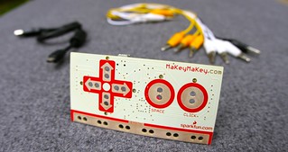 MaKeyMaKey works by sensing current flow through an object, such as a banana, through your body, toward ground.
 But it requires the user to touch a ground wire or contact as well as the object you want to sense.
I was interested in getting rid of the ground wire so I looked into capacitive sensing.
I was interested in getting rid of the ground wire so I looked into capacitive sensing.
Saturday, November 29, 2014
Playing with the MiniQ v2
I recently bought a DFRobot MiniQ v2 to evaluate as a possible pre-built robot to use in the robotics class I'm teaching.

Features
The MiniQ is small, but comes in a nice plastic case with a USB cable. (It also comes with another ribbon cable – I think it is used for add-ons, but not yet sure.) It has an intriguing mix of features:- Built-in wheel encoders
- IR proximity sensors in front
- Left and right ambient light sensors
- An RGB LED (very bright!)
- Five line-following sensors underneath
- Three built-in pushbutton switches
- An HMC5883 compass module
- IR remote control unit (can be read through the IR proximity sensor)
Friday, October 31, 2014
More About Sonar Sensors
Unfortunately, further tests with multiple sonars show that the sonars have a lot of errors, mostly when not pointed directly at a flat surface. That is, if the angle of the sensor to a wall is close to the normal, the sensors are quite accurate. As the angle from normal increases, the incidence of spurious large distances also increases.
As well, there appear to be false echoes off the ground – since my robot has little ground clearance – when the actual distances increase. You can see that from this graph, which shows sonar distances while the robot is moving. The robot path is shown as the blue plot. The sonar positions are left-side (about 80° to the left of straight ahead), left-front (about 10° to the left), right-front (10° to the right), and right-side (80° to the right).


As well, there appear to be false echoes off the ground – since my robot has little ground clearance – when the actual distances increase. You can see that from this graph, which shows sonar distances while the robot is moving. The robot path is shown as the blue plot. The sonar positions are left-side (about 80° to the left of straight ahead), left-front (about 10° to the left), right-front (10° to the right), and right-side (80° to the right).
Friday, October 17, 2014
Sonar Measurements While Moving
I've been worried about two things regarding the sonar sensors, HC–SR04 units:

The wall distance before about 3 seconds was from an intermediate obstacle to the left. Robot distance traveled is based on the wheel encoders, which have 30 segments per revolution, about 7mm per tick. The wall distance was measured by an HC–SR04 sensor pointing forward.
I was expecting a lot more variation in the sonar sensors (distance to wall). The actual values are accurate enough that little smoothing or filtering may be necessary. There are more wiggles in the speeds, because I calculated those based on measurements in the interval, 1/4 second.
Do the sonar sensors interfere with each other if they are fired close together?
Is there electrical noise from firing the sonars that interferes with the measurements?
- The sonars may have a lot of variance in their measurements, according to reports on the web.
- Measurements from the sonars may be affected by movement, or by noise from the motors.
The wall distance before about 3 seconds was from an intermediate obstacle to the left. Robot distance traveled is based on the wheel encoders, which have 30 segments per revolution, about 7mm per tick. The wall distance was measured by an HC–SR04 sensor pointing forward.
I was expecting a lot more variation in the sonar sensors (distance to wall). The actual values are accurate enough that little smoothing or filtering may be necessary. There are more wiggles in the speeds, because I calculated those based on measurements in the interval, 1/4 second.
Further Questions
Do the sonar sensor readings have more variance if the wall is at an angle?Do the sonar sensors interfere with each other if they are fired close together?
Is there electrical noise from firing the sonars that interferes with the measurements?
Friday, October 10, 2014
More About Odometry
A few weeks after I had the odometry working, I found that the robot started veering off course, and it wouldn't follow waypoints as accurately. I was adding sonar sensors at the time and was worried I was getting noise from all the additional wiring. So I researched a little more and experimented with a pull-up resistor instead of a pull-down.
The old wiring:

The old wiring:
With the pull-down resistor, the analog reading on pin A0 ranged from about 30 (black stripe) to about 150 (white stripe), enough to distinguish, but not high enough to use a digital input.
Sunday, September 28, 2014
Odometry
I wanted my robot to be able to do dead reckoning, so I needed wheel encoders. There are some encoders on the market that can work with the Dagu yellow motors, as in the Magician chassis, or with the Solarbotics gear motors. And Pololu makes an encoder for their micro metal gear motors that detects wheel motion and direction by detecting white reflective tabs built-in to the wheels.
But I had already decided to use continuous rotation servos, which don't have a second shaft on the non-drive side to mount an encoder disk. Instead, I decided to mount a paper ring of encoder stripes on the inside of a Solarbotics servo wheel. I needed some way to detect the changes between black and white as the wheel rotated.
I found a set of components from Optek on mouser.com that seemed promising. They were a combination of an LED and a phototransistor, packaged together in a trapezoidal case with a screw hole.
Subscribe to:
Posts (Atom)